|
| |
FLOW MEASUREMENTS FORUM
Flow measurement
professional and users - let's talk and exchange ideas!
How many gallons per minutes are REALLY flowing out of that
pump? Perhaps the OEM pump manufacturer tested this pump at the factory - or
perhaps not. You now have a pump, or it may have been there for some time, and
you suspect it no longer pushes the flow as it used to, or supposed to. What can
you do?
Installing a mag flow meter, or similar, is intrusive -
cutting into the pipe is expensive, not to mention putting everything on a
screeching hold. Instead, an externally mounted flow meter can do a good job.
However, there are tricks to that. Clean liquids require different types of flow
meters and compared to dirty liquids. And, the place you position you meter can
be tricky - not always a 10-15 straight run of pipe is a good thing, as
sometimes an elbow actually (believe it or not) helps, as it creates additional
vortices of which the ultrasonic meter can bounce off the signal, to get a
better reading.
Consider the realities of the field as compared to the air
conditioned office. It is hot, dirty, noisy and you have a deadline to meet:
|
It is hot and humid... I wish I was at the office with
a cup of coffee! |
It is wet, nasty and dirty - I wish I was at the beach! |
It is hard to reach... -
but the client wants to know the flow -
soon!
|
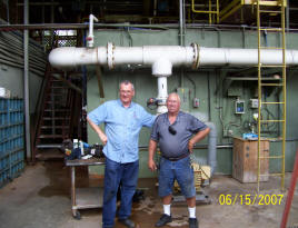
But, at the end of the day the reward is
great - a happy customer and a new friend |
To help
the Flow-Measurement-Community, Pumping Machinery, LLC is partnering with
Instruments Direct, Inc., starting Flow Measurement Forum - to
exchange ideas, compare notes, and learn new tricks - to better understand
what works well, what is practical, and what is not. We will be posting your
emails below, at the "Flow Poster Hints" Board. And, you can get additional
professional help from the folks at Instruments Direct, Inc at:
 - you
will many good additional ideas, information on types of flow meter, and
more. - you
will many good additional ideas, information on types of flow meter, and
more.
Flow Measurement Forum:
Q: Does an
ultrasonic flow meter need to be attached to the pipe with straps?
A: Not really,
although if you plan to do repeated measurement, it would help. For quick
troubleshooting, you can simply hold the sensors in your hands. Make sure,
however, sensors are well lubricated with the appropriate lubricate between
the base of the sensors and the pipe, and keep the pipe clean of rust.
Q: How long does a
battery last typically?
A: Good meters have large
powerful battery, and it lasts a long time, typically (100) hours of busy
measuring work.
The following debate produced very insightful
views, considerations and data. The readers, no doubt, will enjoy this
exchange:
Q:
Lev,
I have enjoyed reading your articles in Pumps & Systems magazine and other
venues for awhile, and appreciate not only your obvious in-depth
understanding of pumps but your willingness to take on accepted conventions
(e.g., the alignment limits discussion of a few months back). I should have
written you to say so before, since what I am about to say takes another
path altogether. We humans find it far too easy to criticize instead of
complement, and I'm afraid I'm stuck in that rut myself.
But I have to say that the ultrasonic flow measurement article in the August
issue (
http://www.pump-zone.com/article.php?articleid=452)
borders on a disaster. A more appropriate title might be "How to get
tricked by flow measurements in the field".
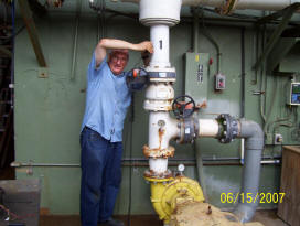
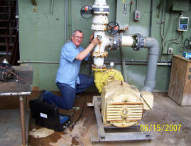
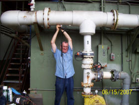
In one photo, you show an attempt to measure flow in the middle of a tee
(with some of the flow potentially going through what appears to be a bypass
line); in another, immediately downstream of a check valve/butterfly valve
series, and in the third, 1-2 pipe diameters after a tee (with an inlet
bushing that approximately doubles the pipe diameter).
I own, and have used several time of flight and Doppler-based instruments in
the field hundreds of times in industrial settings, am quite familiar with
the challenges one runs into in terms of with respect to preferred flow
geometry, and so I don't offer these comments from a lofty academic
perspective. If I used a two channel meter at the third location, with the
two transducer pairs oriented in perpendicular directions, got readings that
matched (within reason), and then moved the transducer pairs both axially
and circumferentially a bit and got consistent readings, then I might
consider using the results, especially if the combination of the pump
power/head curve, motor power and head measurements pointed me in the same
direction (assuming the curve is available, of course). That is, if there
is enough room in that section of pipe for a transit time setup (very
marginal) and I was able to verify that there was no bypass flow through the
first tee, and no flow going to the right in the second tee.
For the other two locations, I'd assume potential errors of at least 20% -
i.e., I probably wouldn't bother. The length of suction line is not shown,
but the photos appear to suggest several feet of suction line. I'd be a lot
more inclined to look there than anywhere in the discharge line for the
application shown.
I would encourage you to consider retracting the article. It could
seriously mislead potential users, especially given your credibility with
respect to what is going on between the pump flanges.
Regards,
Don Casada
Diagnostic Solutions, LLC
Knoxville, TN
A: Don, - I absolutely loved your comments!
I can immediately tell the guy who has “done it” from the guys who
“saw others do it”, - and you are definitely the guy who “done it”! I
especially enjoyed reading the part where you use two locations, then the
third one, and applying perpendicular directions, to see if a group of
readings makes sense. I do the same, and never trust a single reading,
as I have many times seen a 1,000 gpm flow show as 300 gpm! – a “bad” spot.
Finding a “good spot” is a million dollar challenge in the realities of the
field. There is no such a thing as a “good spot”, - exact as at a lab. Thus
one needs to learn to use the imperfect means to obtain answers that lead to
actions. And that is what the spirit of the article is all about.
You took some of my comments, particularly the titles under the photos too
seriously. It was intended to be an entirely opposite point, - i.e.
making a ridicule of a “good” spot: in the first photo (“another example of
a good location…”) the intent is to show the field reality: note that
my knees are literally wet in the mud, the shirt untucked, and the whole
setup is a disaster. That is the field. That is the reality. The word “good”
should have been in parenthesis, but I felt that anyone looking at the
photos will immediately get the point of hardly anything left on the pipe
available for the measurement – certainly nowhere near the 10-15 pipe
diameters, as Mr. Navier-Stokes would demand.
The next photo (“here is an example of a good, easy to reach…”) – is also
meant to be in quotes – as it is obviously not easy to reach – just
note strain and pain on my face trying to keep the darn sensors from falling
off!
The third photo (“mounting the flow meter…”) says it a bit more direct –
hard to reach, as I am nearly stretching my spine out of vertebrae – and the
picture show it. Keep in mind some other places I am sure you worked at –
power plants, paper mills, - with hot, steamy, dirty pipes, hanging over
your head 40 feet up! – try to reach them! I made a point of that within the
article, “given the realities of plant configurations, locating a good spot
to mount a flow meter for troubleshooting can be a real challenge…” – and
the photos are meant to illustrate exactly that – albeit with a bit of a
humor – although I submit you took it too literally.
Now, your concern that my “advice” of applying a flow meter at a “bad” spot,
and thus causing trouble (teaching wrong the young and the restless) to a
poor guy doing it should not be a big issue, for the following reason. Those
who know nothing about these meters usually do not burden themselves with
standing in the mud, on their knees, trying to measure flow. These folks
usually sit at the plant lunch room, reading a newspaper, waiting for a 3:30
pm quitting time. The folks that do know how to apply a flow meter,
understand very well what I am trying to say, as they did it themselves,
many times, and learned to extract good
information (not just good
data) from the flow measurement work. These people do not simply
take a single reading. They read at several locations, at the top, bottom,
sides of the pipe, - before the pump, after, before the bend, at the bend,
after the bend, good spot, not-so-good spot, bad spot, etc - and interpret
the picture that thus evolves, with intelligence and reason. For example, I
often get low flow reading at the top of the pipe. Why? Because that is
where air, if present, tends to accumulate. Air tends to trap inside and
moves slower then the main stream, making a meter think the
overall stream moves slower, and
thus producing a reading of lowered flow. I use this technique to actually
not measure flow, but to find out if there is air in the pipe!
Reading immediately past the elbow is believed (by theoreticians, who never
actually measured any flow themselves) as a bad, bad, bad thing. However,
the vortex that is shed off from flow negotiating a turn is actually helping
the reading, in case of clean
liquids, where Doppler meter usually is not applicable. The error? Yes. I
found out, as you stated, in such cases I can be about 20%, or even 30% off.
Should I discard such method for an error which is WAY off the claimed 0.5%
error ability of the “good” instrument? Maybe not. I had a case where a pump
was beating itself to death, pumping less then 20 gpm, with BEP rated at
about 1000 gpm (!). When I applied the meter (at a bad bad bad spot), I got
something like 70 gpm – way off the actual 20 gpm, - but it proved the point
of a pump indeed operating WAY off to the left of the 1000 gpm BEP, and
corrective action was taken – and that action - is what matters. Thus, not
always a 0.5% accuracy is needed. I have stated this point in my article
clearly, as, at the last paragraph of it, I stated that “…if you are doing
flow certification, this may not be good enough…”, admitting the cases where
the approximate reading are not acceptable.
Finally, to the header portion of your comments, - back to “praise” from the
“criticism”. The cases I describe are always based on my personal
experience. That is what I actually see in the field, - not what I read in
books (I did readings early in my life). And the spirit of my notes is
always a search for facts, - away from emotions. As you pointed out,
my article on alignment, has produced a storm of a debate – but, to this
day, no data proving the 0.002” alignment leads to longer pump life,
as compared to 0.020”. Likewise, in this article on flow, I would now
challenge you (or anyone else) to show (data please!), the differences in
flow readings (a map of flows, please, along the indicated path) for the
following illustration, at the points shown:
Has anyone done such (or similar) flow study (along the pipe path, at
various locations, before, after valves, before, after bends, at top,
bottom, sides, etc.). The diagram does not need to be exactly as I show it,
but “nightmarish enough”, to make a point. A study like that – I will
believe. The words alone, with no data, - next, please.
In conclusion, as I stated at the beginning, - I was absolutely delighted in
your comments, criticism, and, most of all, a detailed path you presented on
how you do field studies yourself, - great examples, and profound point of
using multiple points to get a truer picture, instead a quick-and-dirty
single reading. To do that, one needs to work and to sweat, - in the
field, under a hot sun, away from the air conditioning office.
As Charlie Heald used to tell us, then young engineers, at the good-old
days: “Do Not Listen To Those Who Ain't
Done It!” You have obviously “done it”, and, by all means, have
earned my greatest respect.
When you are in Atlanta (Knoxville is not too far) – stop by, lunch is on
me!
Best regards,
Lev Nelik, Ph.D., P.E., APICS
President / Technical Director
Pumping Machinery, LLC
Follow-up Q:
Lev, thank you for the quick response.
To answer your request for data: I've done a bit of checking under
reasonably controlled conditions to gauge the effect of less-than-desirable
monitoring points. It is certainly less than comprehensive, since that
would involve a host of geometric configurations and flow-disturbing
devices.
I'm attaching some summary data from a recent test that I conducted with a
colleague from Oak Ridge Nat'l Lab, Daryl Cox. This was from a fairly
decent-sized tower water system (serving several chillers). The nominal
pipe size where we made the measurements was 18 inches (17.25" ID). Average
magnetic flow meter indication was 3380 gpm (velocity = 4.64 ft/s, Re of a
bit over 550,000). The elbow in question was long radius, installed in a
horizontal plane, and was preceded by a vertical plane LR elbow about 10 L/D
upstream. The orifice mentioned is a flow-metering orifice (the delta-P
transducer was no longer in service, but the orifice was still in place).
This sort of stuff is at least touched upon in the Dept. of Energy's Pumping
System Assessment Tool (PSAT) workshops (both end-user and specialist). If
you're not familiar with PSAT, it is a software program that is geared
toward using field measurements to assess the potential energy savings. So
naturally, we feel compelled to at least note some of the common pitfalls
associated with not only flow, but pressure, electric power, etc.
measurements.
I also have - somewhere - some other ultrasonic-based data collected while I
still worked at Oak Ridge. This data was in a smaller system, and as I
recall, the piping was 4-inch schedule 40 CS. But I was able to exercise a
bit more control over the operating conditions, since it was in a test
loop. I don't have access to some of my old stuff back at home at the
moment (am spending the summer with my 98-yr old father). But if my feeble
mind can remember, I'll try to dig it out this fall. As I recall (for a
single plane elbow), once I was beyond about 4-5 L/D's downstream, the
errors were under 5%. My undocumented experience has taught me that unless
the disturbance is particularly ugly and/or the velocity/Reynold's number is
unusually high, around 5 L/D's is very acceptable - of course the
reliability of undocumented experience is a bit subjective.
There are some ultrasonic meters, particularly of the single transducer,
Doppler style, that I completely distrust. One feature that I appreciate is
when the meter either tells me that conditions are too ugly to measure or
reports parameters that suggest I should be careful with the data. I hate
it when a meter gives me a reading regardless of the quality of the signals
it is dealing with. I own an inexpensive unit that falls in this category
which I'd be happy to sell (but would probably feel guilty after doing so).
Two channel meters are incredibly valuable, since you can get dual geometry
readings on a single flow path (such as the perpendicular plane arrangement)
or record two paths simultaneously. Both Panametrics and Controlotron (now
GE and Siemens, respectively) have made dual channel units that I've been
very pleased with. Panametrics/GE decided to cut the 2-channel unit from
their product line, so I stick with older stuff from them. There have been
several occasions where I was initially very skeptical about the results
that my old Panametrics PT868 was giving me, but further investigation
revealed that the observed patterns were consistent with what was actually
going on in the system.
As far as the irony that you apparently intended in your article - maybe
it's just because I'm a hillbilly (a certified one, at that), but the irony
completely failed to register for me in either the print or on-line
version. Perhaps a follow-on clarification might be in order.
|
|
Pipe diameters after elbow |
|
|
|
|
|
|
|
|
|
|
Location: |
2D |
4D |
6D |
8D |
10D |
12D, slight misalignment |
12D, aligned |
20D |
Between elbows, horiz |
Between elbows, near vert |
1.5 D after orifice |
9 D after orifice |
|
Error* |
-6.1% |
-5.2% |
-2.3% |
-0.9% |
-2.9% |
-2.8% |
-1.4% |
0.4% |
-4.3% |
-6.6% |
29.9% |
-1.8% |
*
reference flow is from permanently-installed magnetic flow meter with an
excellent upstream (and downstream) profile
Regards,
Don
Follow-up A: Don, - now we are talking! Your actual
test data speaks volumes! What your test data says is:
·
for internally
unobstructed
pipes (no internal blockages, such as orifices, etc.) an error of
less then 3% can be typically achieved after (5) diameters, -
essentially regardless of the number and severity of bends and turns
before the measurement location. However, even at close immediate
proximity after the elbows (such as (2) diameters), the error is
still reasonably small (6%) for most
practical
applications
·
even for internally
obstructed
pipes the error is low, but the distance to the metering location
needs to be increased somewhat, perhaps (8) diameters
·
the only significant error (30% magnitude) can be expected for the
infernally obstructed pipes, where location to the measurement point
is too close (less then (2) diameters)
We now need to clarify what a
practical
application means. One can imagine two scenarios:
1.
Situation where error must be very small
2.
Situations where a larger error can be tolerated
The examples of the first case are: laboratory experiments, gasoline
terminals and stations and residential or commercial water lines,
and similar. In these case, where liquid is sold to the customer, it
is important to keep an error very small – perhaps under 0.5% or so.
No one likes to be overcharged. In these cases, flow certification
is often done with very good accuracy, and thus large error is not
acceptable in these examples. At the pump OEM factory, a good
accuracy of the pump test is another example of such importance:
Hydraulci Institute specs allow very little margin on error on
efficiency (0.5%), and thus flow meter must very accurate and
calibrated. Pump manufacturers' Test Departments do not use the
types of meters we are discussing - instead, a permanently mounted
meters are used, and proper (10-15 dimaters distance, no turns, etc.
Again, keep in mind, this is not the field situation.
Second situation is entirely different, and belongs primarily to a
category of pumps troubleshooting. Here, the answer one seeks is
“What do you do with the result? Should a pump be shut down
immediately as it may be operating dangerously close to shut off
head? Are four pumps operating in parallel have similar
characteristics, or a stronger pump pushes out the weaker units way
to the left of the curve? Is cavitation noise we hear a result of a
pump operating way out to the right of the curve? Etc.
Consider an example of a wastewater treatment vertical turbine
influent pump, is supposed to operate at 3,000 gpm, with BEP point
at 3,500 gpm. A minimum continues stable flow (MCSF) for this pump
is, let’s assume, 1,500 gpm. During troubleshooting, the only
available location on a pipe is similar to the positions I showed on
a photograph in my article, - let’s assume we are measuring within 3
diameters away from the elbow – a “theoretical” no-no. Let’s say my
flow meter reads (at such “bad” location) 2,500 gpm. Would you
consider data unreliable? According to your study, the error at this
distance is roughly 5%, - so perhaps the flow is actually somewhere
between 2,375 gpm to 2,625 gpm – even if we assume double error
(+-5%, instead absolute 5% as you noted). A conclusion you would
thus reach is that this pump operates sufficiently away from a
minimum flow (1,500 gpm), and thus no piping changes, or further
troubleshooting, is required. You thus get the answer, practical and
inexpensive. Doubtfully, the alternative of unraveling insulation 50
feet over your head at a hard to reach space would justify narrowing
the error down to 0.5%, to obtain the range of 2488 to 2512 gpm.
My very point is that, when troubleshooting, one needs to focus on
actionable results, not a Ph.D. dissertation on flow dynamics. In
such cases, the question to be asked is more “why we do this?”
instead of “how we do this?” Before you ask “how?” you need to first
ask “why?”.
Your point about a single transducer is well taken, and I absolutely
share your view on this. I used to have a single transducer as well,
and got rid of it. Indeed, it gives you a reading, without telling
the strength of a signal or quality of it. The 2-transduer unit I
use has several indicators on single strength and quality, and I
learned not to accept the data when these are weak, and I move the
pick-ups around until I get a signal strength and quality I trust, -
and only then I record the reading of flow.
I am also not really comfortable with “classical” recommendation of
differentiation between Doppler and resident time meters, to apply
for dirty versus clean water. In theory, this would mean having and
using one of which. However, I do not think a truly “clean” water
exists nay more in this world, and if so, it is extremely rare. In
reality, some ingredients (sand, bubbles, etc.) always present,
which, to me, justified using Doppler units, and I prefer them
better then transient time units. That, however, I admit, is a
matter of preference, and individual experience, and it looks like
you prefer transient time better, and have issues with Doppler.
That’s ok.
In consultation, I want to thank you again, for a most delightful,
thought-provoking input. Please be sure that the next time when I
run into a particularly difficult case like this, - you and Brent
will be the guys I will call for help and advice.
Best regards, and most respectfully,
Lev Nelik
Lev Nelik, Ph.D., P.E., APICS
President / Technical Director
Pumping Machinery, LLC
Atlanta, GA
Comments from
Brent Baird,
Instruments Direct, Inc, Woodstock, GA:
As I have previously indicated, your approach does not apply
accepted flow metering practices. So I am not surprised someone
is tossing stones at you.
The text-book answer for a water application would be to go down
stream and find 10 to 15 pipe diameters and installed a
Ultrasonic Transit time flow meter or a Custom Doppler mounted
after a 90 degree elbow. But, if this application does not
exist… do you walk away from the project or do you do a "Nelik
Flow Survey"? My take-away from your unique experiences is that
you become "one with the flow meter", take flow samples from
multiple points and apply your years of pump flow hydraulics
experience and come-up with some flow data. Your successes may
be unique to you and not repeatable to others. But it is your
uniqueness to solve pump issues that attracts customers to you.
Brent Baird
Instruments Direct, Inc
Woodstock, GA
www.instrumentsdirect.com
Q: Dr. Nelik,
Can you refer me to one of your articles or answer a question
about what factors affect when full liquid recovery occurs after
a pump discharge or 90 degree elbow. I know the rule of thumb
has always been 10 pipe diameters, but have never known what
that is based on. The application is five feet per second,
ambient temperature water. We're wondering how to determine the
number of pipe diameters for that specific situation. Pipe sizes
are 2" to 4".
The problem comes up as a result of ball check valve rattle
during pumping.
Thank you.
Jerry Ballard
Energy Equipment, Inc.
Midlothian, VA
Answer:
Jerry,
- the 10 diameters rule has always been a textbook classic, but
in the real world, unfortunately, it ism difficult to come up
with such ideal laboratory situation. Sharp bends, turns,
restrictions, etc. are the field realities. There are two main
considerations for that:
a.
Does the non-uniform flow cause damage?
b. Can such flow be measured accurately, and if so, how
accurately?
Regarding the damage, - the main concern here is the entrance,
not the exit, from the pump. Non-uniform, disturbed turbulent
flow causes issues for the pump inlet: cavitation, pulsations,
vibrations, seal and bearing damage, etc. Here, the rules of the
proper flow approach to the pump are critical.
On the discharge side, however, this is less critical, but can
affect the accuracy of the instrumentation readings. I have
studied the effect of the pipe length for cases of non-standard
lengths, and you can read at sections above.
Friction losses increase with the degree of disturbance, but
these are not the main issue. The issues are the accuracy of the
readings, and absence of pulsations which would cause pump
damage, - a much more significant considerations. In the field,
in the majority of troubleshooting situations, the 5% accuracy
is well enough, and reduced distances of the L/D are fine, as
long as one understands the implications. For some relatively
rare cases, this accuracy is not good enough, for example
metering of the gasoline dispensed to the terminals, requires
perhaps 0.5% accuracy, or even better, and when such needs are
prevent, the attention to the proper L/D, straight runs, smooth
turns, etc. become more important.
Regards,
Lev Nelik, Ph.D., P.E.
President / Technical Director
Pumping Machinery, LLC
Atlanta, GA
Tel. 770-310-0866
Fax. 770-350-9311
email
DrPump@PumpingMachinery.com
web
www.PumpingMachinery.com
Lev,
Thank
you for your information.
Jerry
For
more information, pump sizes, price and deliveries:
 www.PumpingMachinery.com
tel:
+972-50-865-0451 www.PumpingMachinery.com
tel:
+972-50-865-0451
|
 Pumping
Machinery Consulting and Training
Pumping
Machinery Consulting and Training